

 English
 русский
 中文简体

In industrial cooling systems, water is both the most essential element and the most common source of operational problems. Scale, corrosion, fouling, and micr...
READ MORENov 14, 2026
Content
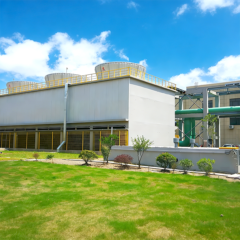
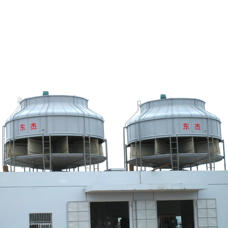
Induced draft cooling towers are the quiet workhorses behind many industrial processes. You will see them at power stations, chemical plants, steel mills, and large HVAC plants, often as a plume of warm, moist air rising from a fan stack. Their job is simple to describe but demanding to engineer: reject waste heat from circulating water by evaporating a small fraction of that water, while a fan pulls air through the tower in a controlled way.
At Dongjie, we design and build cooling towers for projects that cannot afford guesswork. This guide explains how induced draft towers work, the main configurations, what to check during selection, and how to keep them performing over years of service.
In an induced draft tower, the fan sits at the air outlet, usually on top of the tower, and pulls air upward through the fill. Hot process water is distributed over the fill and falls as a thin film or droplets. Air moves through the same volume, contacts the water, and carries heat away. Most of the cooling comes from evaporation: a small percentage of the water changes phase, absorbing latent heat from the remaining water and lowering its temperature.
The fan creates a slight negative pressure inside the tower. That matters because air is drawn in through louvers around the base or sides, then passes through the fill and drift eliminators before leaving the stack. The negative pressure helps keep airflow distributed across the fill and reduces the chance of moist air recirculating back into the inlet. It also means the fan handles warm, humid exhaust air, which is one reason fan selection and material protection deserve attention.
An induced draft tower is not just a box with a fan. Water distribution, fill geometry, drift elimination, inlet louver design, and structural detailing all influence thermal performance, pressure drop, and maintenance access. A tower that looks similar from the outside can behave very differently after a few seasons if these details are not coordinated.
Most induced draft towers follow one of two air-water arrangements. In counterflow towers, air flows upward while water falls downward. This countercurrent contact gives efficient heat transfer and a compact footprint, which is why counterflow induced draft towers are common in industrial cooling. In crossflow towers, air moves horizontally through the falling water. Crossflow layouts can simplify access to some components and suit certain site constraints, but they usually need more plan area for the same duty.
Both arrangements can be factory-assembled or field-erected, and both can use FRP, steel, or concrete structures depending on project scale and site conditions. For an industrial circular counterflow unit, our BLS-II J series is a good example of how a compact induced draft layout can be packaged for demanding process duty.
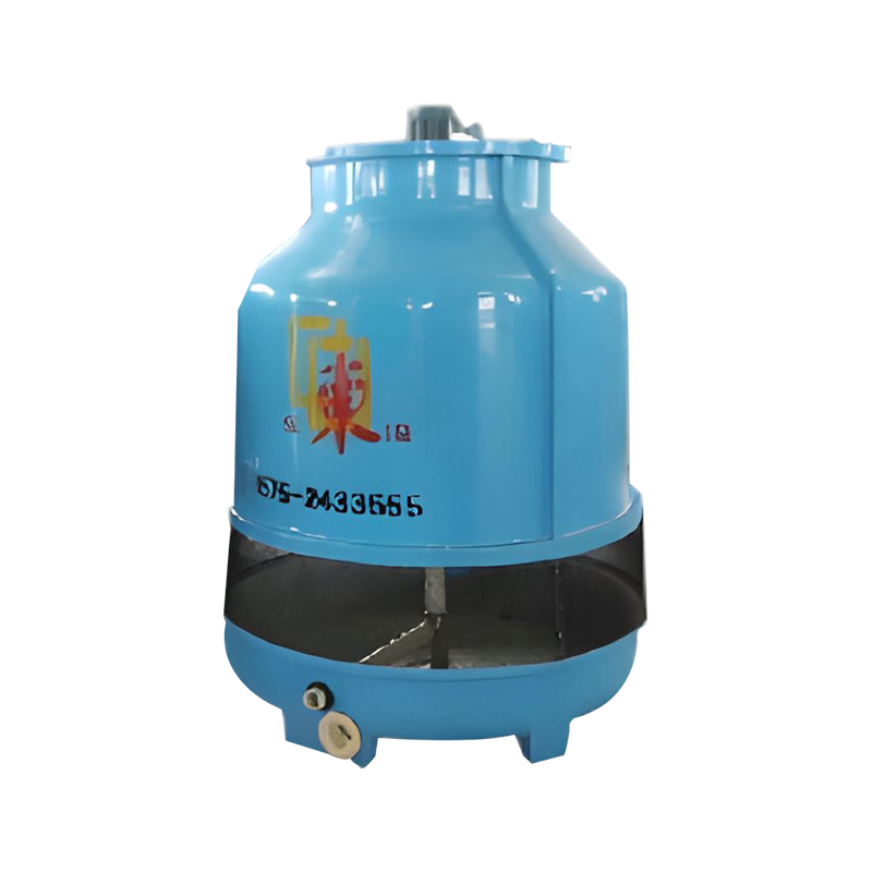 BLS(II)J Industrial Circular Counterflow Cooling TowerCompact induced draft unit with FRP body, stainless steel fittings, and matched fan/motor for demanding industrial process cooling.View Product →
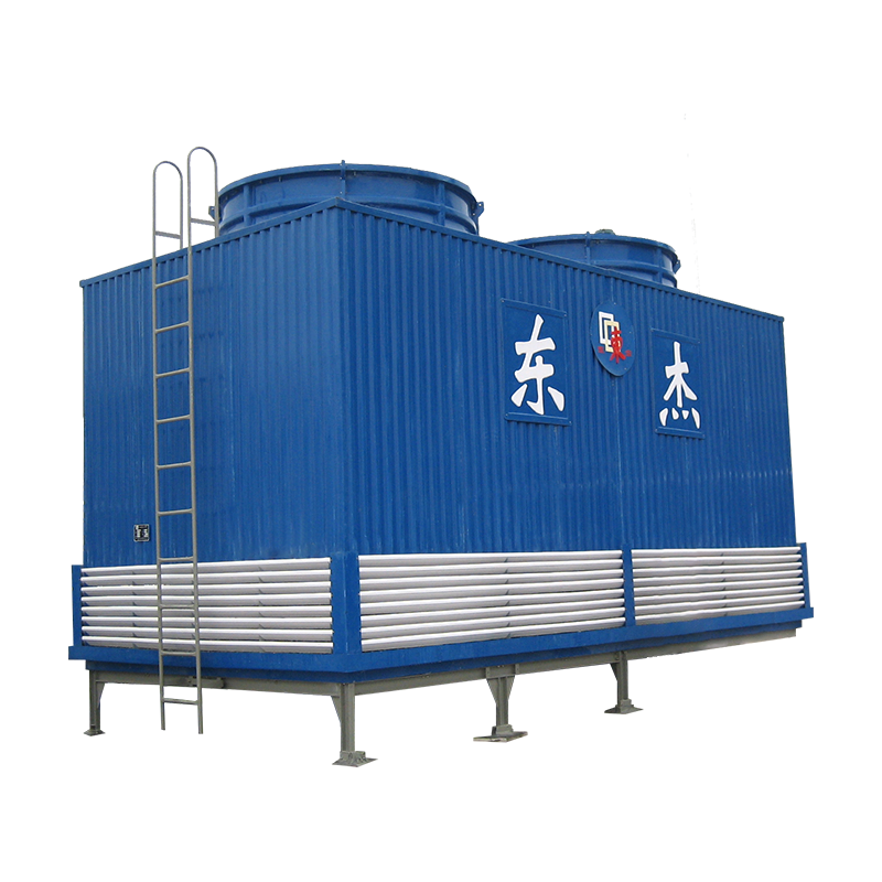
When footprint is tight and the duty is large, rectangular FRP composite towers often make sense. The DV series uses a counterflow arrangement in a rectangular FRP composite structure, which can help with layout, corrosion resistance, and site assembly.
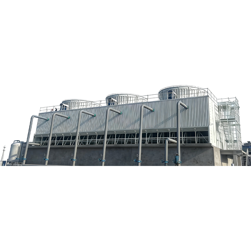 DV Series Rectangular Counterflow FRP Cooling TowerPultruded FRP rectangular tower for tight footprints and large duties, offering corrosion resistance and lightweight on-site assembly.View Product →
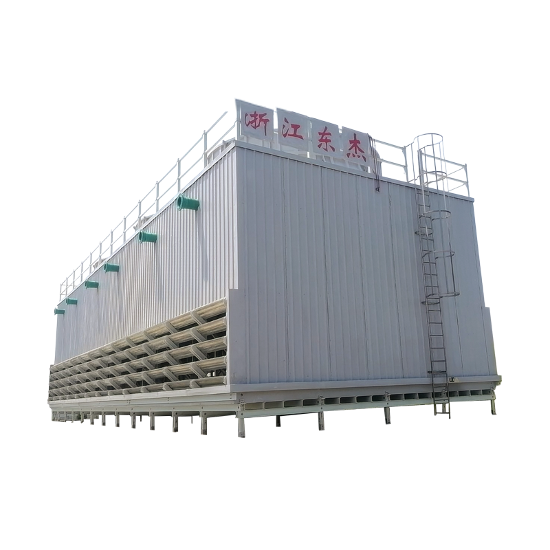
For very large projects where structural height and wind load matter, steel structure towers such as the DF series offer another route. Steel framing can support tall stacks and large fan decks while keeping access routes clear for inspection and maintenance.
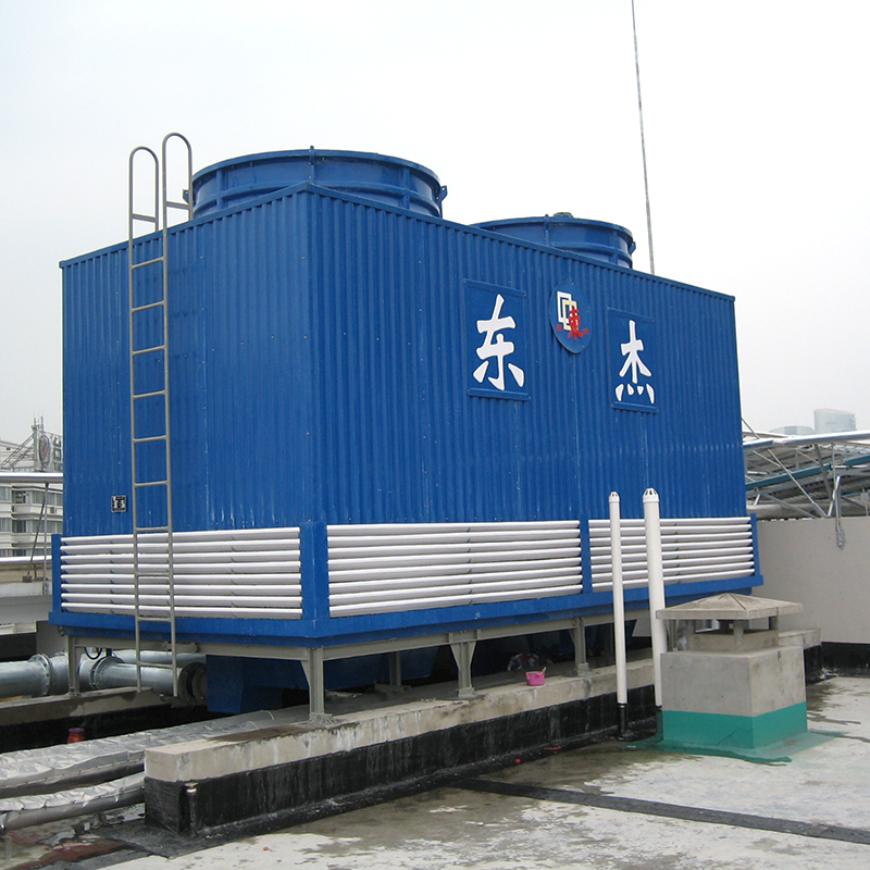 DF Series Counterflow Steel Structure Cooling TowerSteel-framed counterflow tower suited to large projects where structural height and wind load matter, with access for inspection and maintenance.View Product →
A typical induced draft tower includes several interacting parts:
Each component interacts with the others. For example, a tighter approach temperature may require more fill, more airflow, or both. Increasing airflow can raise fan power and drift potential. Good design balances these trade-offs instead of optimizing one item in isolation.
These towers are used wherever a project needs reliable heat rejection from a circulating water loop. Common sectors include power generation, petrochemicals, metallurgy, chemical processing, HVAC, new energy, and environmental projects. The duty may be continuous, seasonal, or batch, and the tower may serve an open loop or a closed circuit.
Site conditions often decide the configuration more than the catalog does. Available footprint, prevailing wind, nearby buildings, noise limits, plume visibility, water quality, and winter operation all shape the final design. In cold climates, freeze protection and basin heating may be needed. In dusty or fibrous environments, inlet screens and accessible fill sections help maintenance. In coastal or chemical sites, corrosion protection moves to the top of the list.
Start with the heat load and water flow, not with a model number. You need the inlet and outlet water temperatures, design wet-bulb temperature, approach, range, site elevation, and any process constraints. The required approach—how close the cold water temperature comes to the wet bulb—has a strong effect on tower size and cost. A tighter approach usually means more fill volume, more airflow, or both.
Then check fan power, noise, drift rate, plume behavior, make-up water quality, and available electrical supply. Structural loads, wind and seismic requirements, and maintenance access should be reviewed early, because they can change the tower type or layout. If you are comparing offers, it helps to use a consistent set of key technical indicators for cooling tower purchasing rather than comparing headline price alone.
| Feature | Induced draft | Forced draft |
|---|---|---|
| Fan location | At air outlet, usually top | At air inlet, usually base |
| Pressure inside tower | Slightly negative | Slightly positive |
| Airflow path | Air pulled through fill and drift eliminators | Air pushed through fill |
| Maintenance consideration | Fan works in humid exhaust air; drive access needs planning | Fan near inlet; recirculation and uneven flow need attention |
| Typical fit | General industrial cooling, compact layouts, stable airflow | Specialized layouts where fan placement is an advantage |
Induced draft towers are mechanically simple, but they reward routine attention. The fan drive, gearbox oil level, belt tension or coupling alignment, vibration, and blade condition should be checked on a scheduled basis. Water distribution nozzles can plug or wear, causing uneven flow over the fill. Drift eliminators can become damaged or fouled, which raises drift loss and can affect plume behavior. Basin screens, make-up valves, and blowdown control deserve the same attention as the fan.
Water treatment is part of tower performance, not a separate topic. Scale, corrosion, and biological growth affect heat transfer and structural life. A treatment program should match the water source, metallurgy, and operating cycle. During inspections, look for fill fouling, louver damage, structural corrosion, and sediment in the basin. Small issues are easier to correct before they affect thermal performance or force unplanned downtime.
The best induced draft cooling tower is not the one with the largest fan or the lowest first cost. It is the one whose thermal duty, layout, materials, and maintenance access match the project over its full service life. That usually means a clear specification, a design that respects site conditions, and a manufacturer who can support the installation and the years that follow.
At Dongjie, we work with project teams to match induced draft cooling tower configurations to real operating conditions. Our product range covers circular, rectangular FRP composite, closed circuit, large civil, and steel structure towers, and our factory includes indoor assembly capacity for large units. If you are planning a new cooling loop or replacing an aging tower, the most useful first step is a frank review of duty, site, and operating constraints.
Related Products
In industrial cooling systems, water is both the most essential element and the most common source of operational problems. Scale, corrosion, fouling, and micr...
READ MOREWhen a process line needs to hold a reactor at 5 °C, a chiller is the obvious choice. When the same plant needs to reject a large amount of waste heat from a c...
READ MOREA cooling tower rarely fails all at once. What often happens is quieter: the cold water temperature creeps up by a degree or two over a season, drift becomes v...
READ MOREA plant engineer managing a 2 MW injection molding process was facing a familiar problem. The open cooling tower was letting suspended solids into the mold coo...
READ MOREIf you have ever asked “how does the cooling tower work?” you are not alone. At Zhejiang Dongjie, we work with engineers and plant operators who use cooling to...
READ MOREIndustrial cooling is among the largest consumers of energy and water in the global manufacturing economy. Chillers, cooling towers, heat exchangers, and proc...
READ MORE
dj@djcoolingtower.com
+86-0575-82433555 (Extension 0)
+86 130 6551 5158 Manager Zhang
