

 English
 русский
 中文简体
中文简体

A plant engineer managing a 2 MW injection molding process was facing a familiar problem. The open cooling tower was letting suspended solids into the mold coo...
READ MOREAug 28, 2026
Content
A cooling tower rarely fails all at once. What often happens is quieter: the cold water temperature creeps up by a degree or two over a season, drift becomes visible at the fan stack, or the fan motor draws more current at the summer peak. In many cases the cause is a single component — fouled fill, clogged spray nozzles, or warped drift eliminator blades — not the tower as a whole. That is why a working knowledge of the components of a cooling tower is not just an engineering exercise. It determines how you write a specification, how you compare quotations, and how you budget maintenance for the next two decades of operation.
This guide organizes those components into five functional groups, explains how their arrangement changes across counterflow, crossflow, and closed-circuit designs, and closes with the component-level checks that carry significant weight during procurement.
A cooling tower rejects heat by evaporation. Warm water returning from a chiller condenser or an industrial process is distributed over heat transfer surfaces while a fan drives ambient air through the falling water. Roughly one percent of the circulating flow evaporates for every 5 to 6°C of cooling, and that phase change carries the heat out of the system. The cooled water collects in a basin and returns to the process, closing the loop.
Every part of the tower belongs to one of five groups:
If one group underperforms, the whole tower pays for it. A fan running below rated capacity starves the fill of air. Blocked nozzles leave dry patches where scale forms fastest. A degraded eliminator lets water escape as visible plume and raises make-up water demand across the site.
Fill is where heat exchange actually happens, so it deserves the closest look. By splitting water into thin films or small droplets, fill multiplies the wetted surface exposed to the air stream. Film fill — closely spaced PVC sheets with engineered flute geometry — is the default for clean water because it delivers high thermal performance in a compact volume. Splash fill, made of grid bars or slatted panels, gives up some efficiency but tolerates water with high suspended solids that would clog film fill within a season. Sheet spacing, flute angle, and fill height all trade cooling capability against clogging risk, and the right answer depends largely on your water quality.
In counterflow towers, pressurized nozzles on a pipe network above the fill spray water downward. In crossflow towers, water fills a distribution basin at the top of the tower, then descends through nozzles or metering orifices by gravity. Even distribution matters more than many buyers expect, because dry spots in fill become scale zones, and scale is expensive to remove. Nozzle material, operating pressure, and access for cleaning should be explicit line items in any specification.
Drift eliminators force the leaving air to change direction several times so entrained droplets strike a surface and drain back into the tower. Modern PVC designs hold drift well below 0.001 percent of circulating flow, which protects nearby equipment, walkways, and plume-sensitive surroundings. Blade spacing affects pressure drop, so the eliminator should be matched to the fan rather than bought as an afterthought.
Louvers across the air inlet face block water splash-out, shade the basin from sunlight to limit algae growth, and in cold climates reduce the icing that forms when recirculated moist air freezes at the inlet. PVC and FRP are the standard materials because both resist the constant wet-dry cycling at this location.
Most towers use axial fans mounted at the top for induced draft or at the inlet for forced draft. Power reaches the fan through a gearbox and driveshaft, a belt drive, or a direct-drive motor, which reduces gearbox oil maintenance and belt stretch but demands a motor enclosure rated for warm, saturated air. FRP fan blades have largely displaced aluminum in industrial service because they weigh less, resist corrosion, and can be molded into efficient aerodynamic profiles.
The casing encloses the internals and withstands weather plus water chemistry. The frame carries the fill, fan, and live loads. The basin collects the cooled water and typically houses a suction screen, make-up valve, and overflow and drain connections. These three elements define how long the tower survives in your environment, which is why material selection is a decision that outlasts many other decisions.
| Component | Primary Function | Common Materials | Typical Failure Mode |
|---|---|---|---|
| Fill media | Spreads water into films or droplets to maximize evaporation surface | PVC, polypropylene, splash grids | Fouling, scaling, collapsed sheets |
| Nozzles and distribution | Delivers water evenly across the fill or coils | ABS, polypropylene, stainless steel | Clogging, uneven spray pattern |
| Drift eliminators | Captures entrained droplets from the leaving air | PVC, FRP | Warped or brittle blades raising drift |
| Inlet louvers | Blocks splash-out, sunlight, and inlet icing | PVC, FRP | Cracking and UV surface erosion |
| Fan and drive | Moves ambient air through the tower | FRP or aluminum blades, steel shafts | Bearing and gearbox wear, belt stretch |
| Casing and frame | Encloses internals and carries structural loads | FRP, hot-dip galvanized steel, concrete | Corrosion, UV degradation |
| Cold water basin | Collects cooled water for return to the process | Concrete, steel, FRP | Leaks, sediment build-up, algae |
The same components appear in every evaporative tower; what changes is their arrangement, and that arrangement drives footprint, pump head, and maintenance access.
Air travels vertically upward while water falls downward through the fill. Because water is sprayed under pressure from pipes above the fill, no top distribution basin is needed, and the plan area stays compact — a real advantage where space is tight. The trade-off is that internal access for cleaning the distribution system is more awkward, usually through ladders and hatches.
Air moves horizontally across vertically falling water, entering through louvers on two or four sides. Gravity-fed distribution basins keep pump head low and let maintenance staff inspect nozzle performance while the tower runs. Crossflow designs occupy more ground area but offer easier access to the components that need attention frequently.
A closed-circuit tower keeps the process fluid inside a sealed coil bundle while sprayed water and moving air cool the coil exterior. The process loop stays clean, loses very little fluid to evaporation, and avoids contamination from the recirculating spray water. In this configuration, the coil bundle takes over the fill's role as the primary heat transfer surface, while spray nozzles, drift eliminators, fans, and the basin keep their usual jobs. The DBN-series closed circuit counterflow cooling tower is a representative industrial specification of this arrangement, pairing a counterflow envelope with a pressurized spray system over the coil bundle.
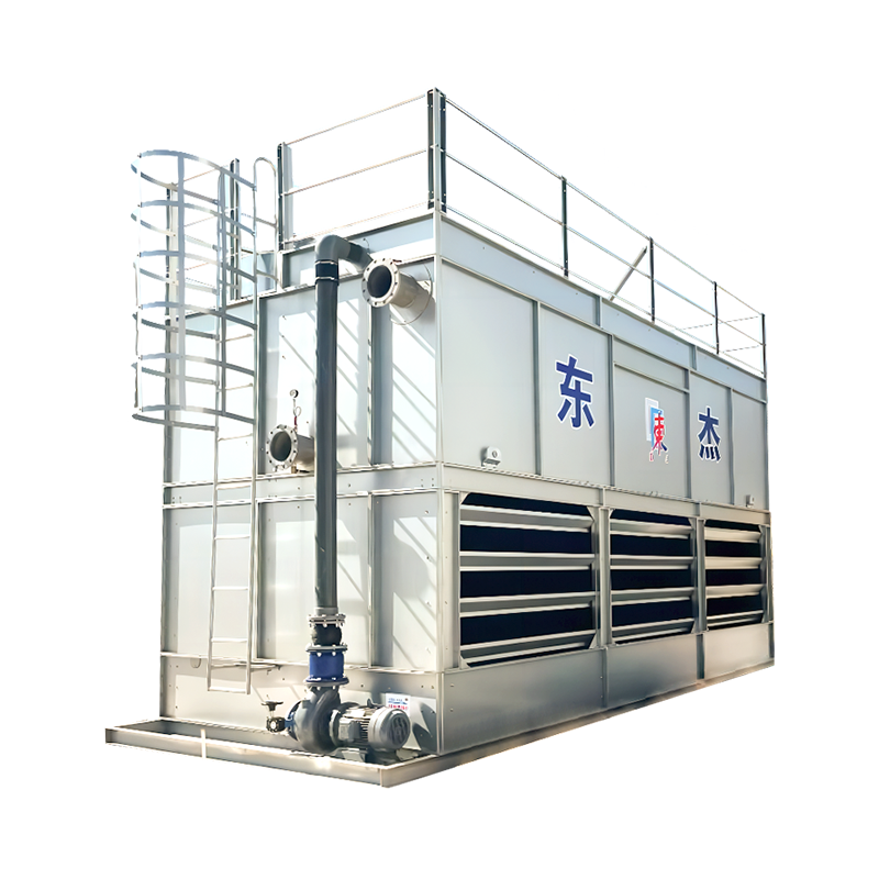
 DBN Series Closed Circuit Counterflow Cooling TowerThis counterflow closed-circuit tower keeps process fluid inside a sealed coil bundle while sprayed water and air cool the exterior, preserving water quality and reducing loss—worth reviewing as the article explains how the coil bundle replaces fill as the primary heat transfer surface.View Product →
Materials decide how long each component survives your water chemistry and atmosphere, and this is where manufacturers separate themselves clearly.
FRP casings resist attack from water treatment chemicals and industrial atmospheres, resist rust and rot, and hold dimensional stability across temperature swings. The same logic extends to pultruded FRP structural members, ladders, and fan blades. Buyers comparing rectangular counterflow designs should look at how the DV-series rectangular counterflow FRP composite cooling tower combines an FRP shell with a corrosion-free internal structure, since that combination significantly reduces the casing as a maintenance item.
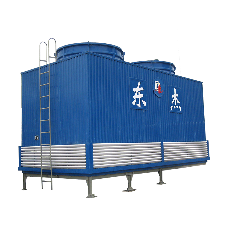
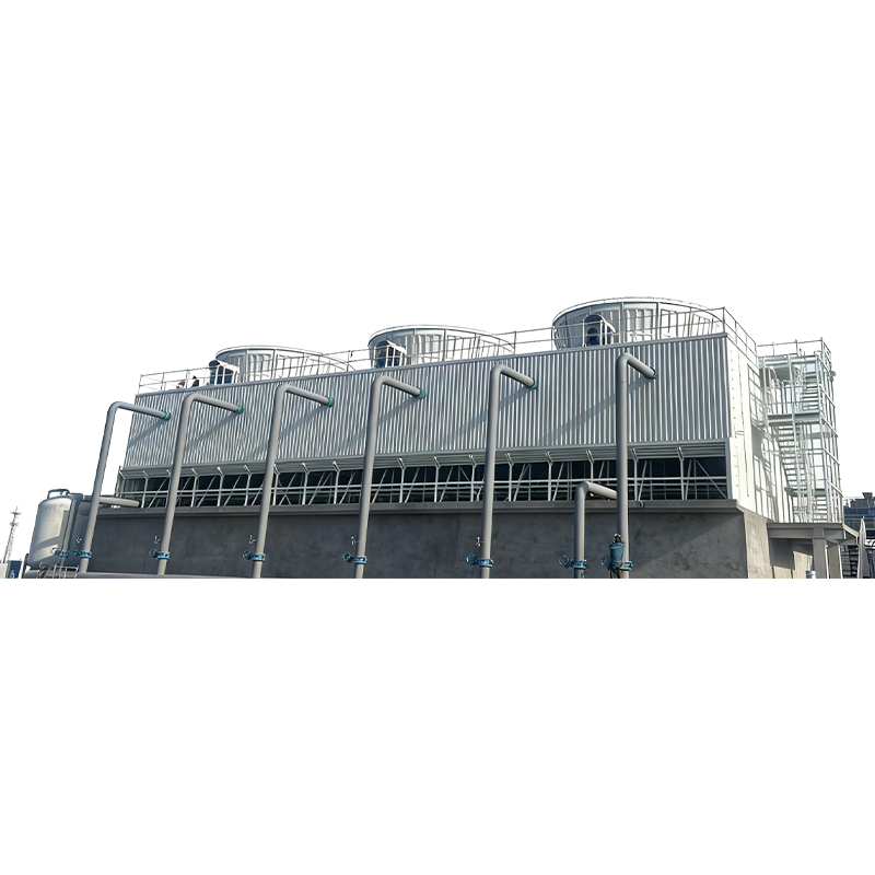 DV Series Rectangular Counterflow FRP Composite Cooling TowerCombining an FRP casing with a corrosion-free internal structure, the DV-series tower significantly reduces the shell as a maintenance item. It fits the article's discussion of FRP's chemical resistance and dimensional stability in industrial water chemistry and atmospheres.View Product →
Hot-dip galvanized steel remains the economical choice for large frames, particularly where span and load demand its stiffness, and stainless fasteners at every connection extend joint life considerably. Very large civil and power projects often go further, using all-concrete basins and towers or steel-concrete hybrids designed for multi-decade service. Where a project calls for steel construction, the counterflow steel structure cooling tower illustrates how a galvanized frame is engineered around corrosion protection and modular erection on site.
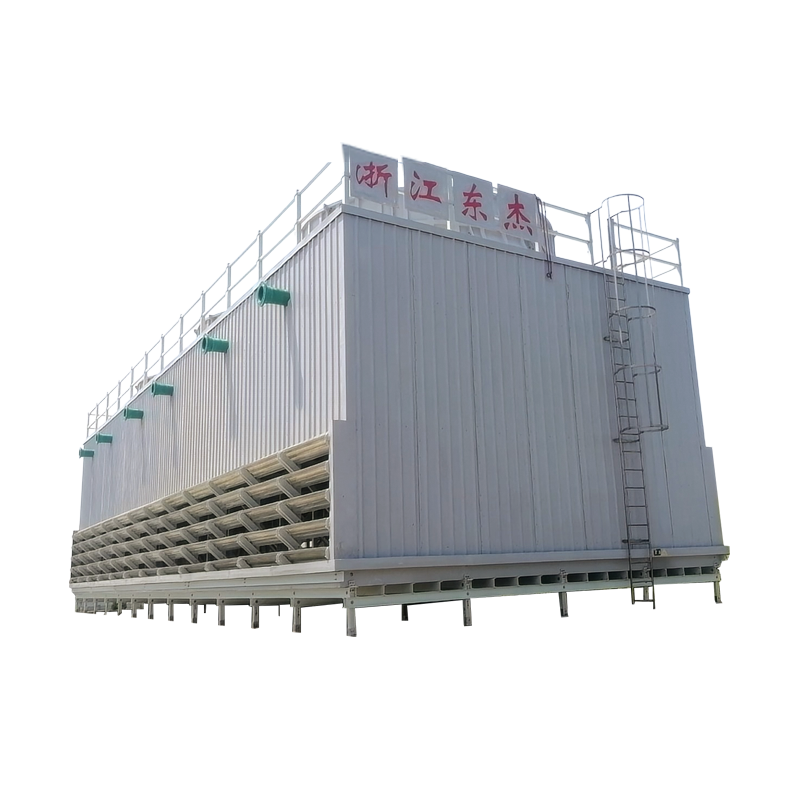
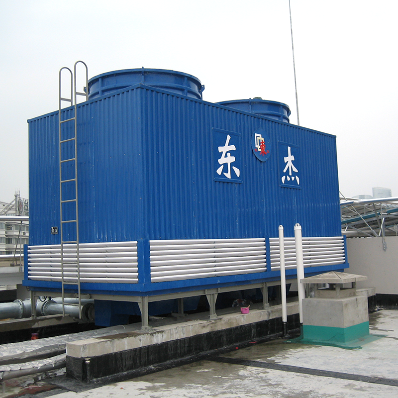 DF Series Counterflow Steel Structure Cooling TowerA galvanized steel frame tower engineered for corrosion protection and modular on-site erection, illustrating the article's point on material selection—hot-dip galvanizing for large spans and loads, with joint durability deciding long-term service life.View Product →
Start with the conclusion: two towers with identical rated capacity can differ by double-digit percentages in lifetime cost, and the difference is almost entirely component-level. Fill quality sets thermal performance for its installed life; drift rate sets water consumption; the drive system sets maintenance hours; casing and basin materials decide whether the structure reaches year twenty without major intervention.
Before signing, score each quotation against these checks:
A practical way to run the comparison is to score every offer line by line against the key technical indicators to consider when purchasing a cooling tower, so component differences become visible instead of buried under headline pricing. A cooling tower is typically a fifteen-to-twenty-five-year asset, and the components you approve today determine the water bills, fan power, and maintenance hours you will pay long after the purchase order is closed. A specification that names materials and demands testable guarantees ages far better than one that awards on price alone.
Related Products
A plant engineer managing a 2 MW injection molding process was facing a familiar problem. The open cooling tower was letting suspended solids into the mold coo...
READ MOREIndustrial facilities, commercial buildings, and power generation plants all share a common operational challenge, the need to efficiently remove excess heat g...
READ MOREIn industrial cooling systems, water is both the most essential element and the most common source of operational problems. Scale, corrosion, fouling, and micr...
READ MOREWhen a process line needs to hold a reactor at 5 °C, a chiller is the obvious choice. When the same plant needs to reject a large amount of waste heat from a c...
READ MOREIf you have ever asked “how does the cooling tower work?” you are not alone. At Zhejiang Dongjie, we work with engineers and plant operators who use cooling to...
READ MOREIndustrial cooling accounts for nearly a fifth of global electricity consumption. As climate targets tighten and energy costs surge, the race toward high-effi...
READ MORE
dj@djcoolingtower.com
+86-0575-82433555 (Extension 0)
+86 130 6551 5158 Manager Zhang
