

 English
 русский
 中文简体

In industrial cooling systems, water is both the most essential element and the most common source of operational problems. Scale, corrosion, fouling, and micr...
READ MORENov 19, 2026
Content
If you have ever opened a drawing set and followed a pipe only to lose it behind a pump symbol, you are not alone. A chiller and cooling tower diagram can look busy at first—pipes, valves, pumps, and arrows moving in every direction. Once you read it as a heat-rejection map, though, the picture becomes much calmer. The chiller removes heat from the building or process, and the cooling tower releases that heat to the atmosphere. The diagram shows where the water goes, where the refrigerant goes, and how the two machines stay in step.
A chiller does not create cold. It moves heat from one place to another. Inside the chiller, the evaporator absorbs heat from the chilled water loop. The compressor raises the refrigerant pressure and temperature, and the condenser rejects that heat into the condenser water loop. The cooling tower then rejects the condenser water heat to the outdoors through evaporation.
That is why a good diagram is more than a layout. It is a story about energy moving in one direction and water moving in two closed loops. The arrows should tell you which side is warm, which side is cold, and where the two systems meet.
Most water-cooled chiller diagrams show three loops. They are separate, but they depend on each other.
This loop runs from the chiller evaporator to air-handling units, fan coils, or process heat exchangers. Warm return water comes back to the evaporator, gives up its heat, and leaves as colder supply water. The chilled water pump and control valve positions are usually marked on the diagram.
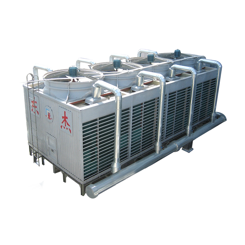
The condenser water loop connects the chiller condenser to the cooling tower. Water leaves the condenser warmer, travels to the tower, is distributed over the fill, and returns cooler. The condenser water pump, strainers, valves, and tower basin all belong to this loop. This is where tower selection really shows up: flow rate, supply and return temperatures, approach, and range all have to line up with the chiller.
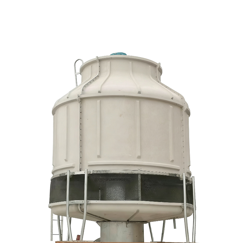
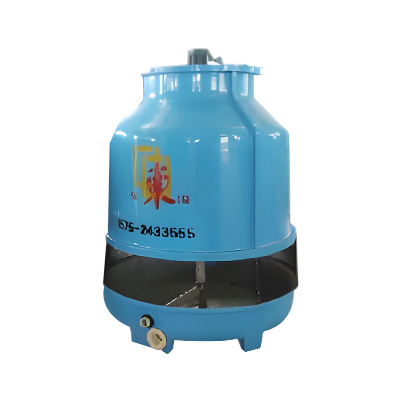 Industrial Circular Counterflow Cooling Tower (BLS(II)J Series)Fiberglass circular counterflow tower with automatic rotating distribution and low-noise operation, suited to condenser-water loops where flow and temperatures align with the chiller.View Product →
The refrigerant loop stays inside the chiller package. It includes the evaporator, compressor, condenser, expansion device, and accessories. Many system diagrams simplify this loop to a box labeled “chiller” because the refrigerant circuit is the manufacturer’s scope. Even so, the diagram should show where the refrigerant gives up heat to the condenser water and where it absorbs heat from the chilled water.
The table below is a quick reference for the symbols and labels you will meet most often.
| Component | Loop | Role in the Diagram |
|---|---|---|
| Chiller evaporator | Chilled water | Absorbs heat from the chilled water loop |
| Compressor | Refrigerant | Raises refrigerant pressure and temperature |
| Chiller condenser | Refrigerant and condenser water | Rejects heat to the condenser water loop |
| Expansion device | Refrigerant | Drops refrigerant pressure before the evaporator |
| Chilled water pump | Chilled water | Moves supply water to loads and return water back to the chiller |
| Condenser water pump | Condenser water | Moves water between the chiller and the cooling tower |
| Cooling tower fill | Condenser water | Creates surface area for evaporation and heat rejection |
| Tower fan | Air side | Moves air through the tower |
| Tower basin | Condenser water | Holds water for pump suction and makeup |
| Control valve or VFD | Both water loops | Adjusts flow or fan speed to match load |
When you read a diagram this way, the equipment symbols start to make sense. The chiller is the heat mover. The tower is the heat rejecter. The pumps are the connection between them.
A water-cooled chiller diagram includes the condenser water loop and cooling tower. An air-cooled chiller diagram does not. Its condenser rejects heat directly to outdoor air, so you will see fans and coils instead of a tower and condenser water pump. Both arrangements are common, but they tell different stories about space, efficiency, and maintenance.
Larger plants often show a primary pump at the chiller and a secondary pump at the distribution loop, with a decoupler between them. The decoupler protects flow through the chiller while the secondary loop varies with building load. If you see two pump sets and a short bypass line, this is likely what the designer intended.
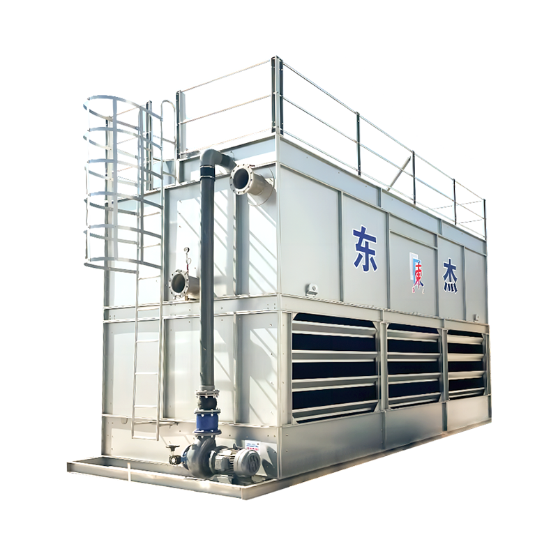
In a closed-circuit tower, the process fluid stays inside coils and does not contact the atmosphere. Spray water runs over the coils and evaporates, and a fan moves air through the tower. The diagram will show a closed process loop, a spray pump, and a basin. This arrangement is useful when the process fluid must stay clean or when freezing and contamination are concerns.
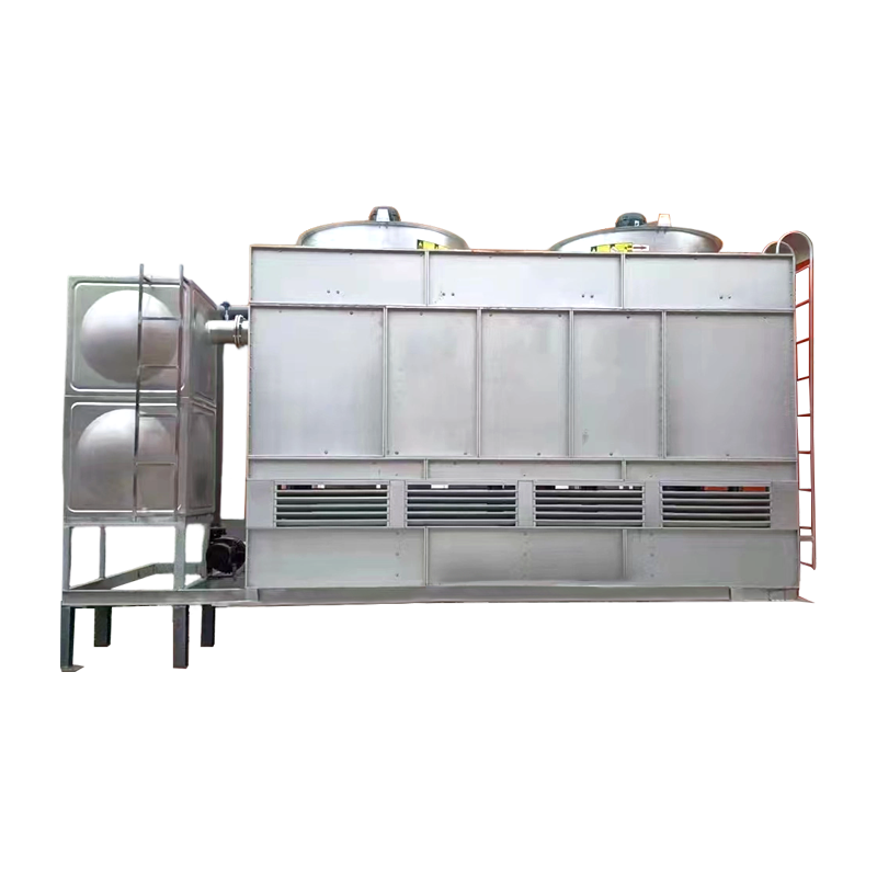 Closed Circuit Counterflow Cooling Tower (DBN Series)Closed-loop counterflow tower keeps process water in pipes, reducing contamination and scaling while offering compact layout and water-saving operation for clean or freeze-sensitive circuits.View Product →
Modern diagrams often include variable-frequency drives on fans or pumps, bypass valves for temperature control, and control sequences in a schedule. These details matter because they affect turndown, energy use, and how the tower behaves at part load.
A diagram is not a selection sheet, but it carries the numbers that drive one. Look for design flow rates, supply and return temperatures, design wet-bulb temperature, tower approach, tower range, chiller tonnage, and redundancy. If the drawing shows a bypass or a three-way valve, check how it affects flow through the tower and the chiller.
The condenser water flow and temperature difference are especially important. A tower selected on the wrong flow or approach can force the chiller to work harder than the diagram suggests. Before you approve the drawing, it is worth checking the technical indicators that matter when buying a cooling tower against the schedule.
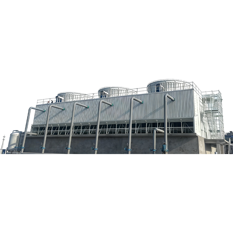
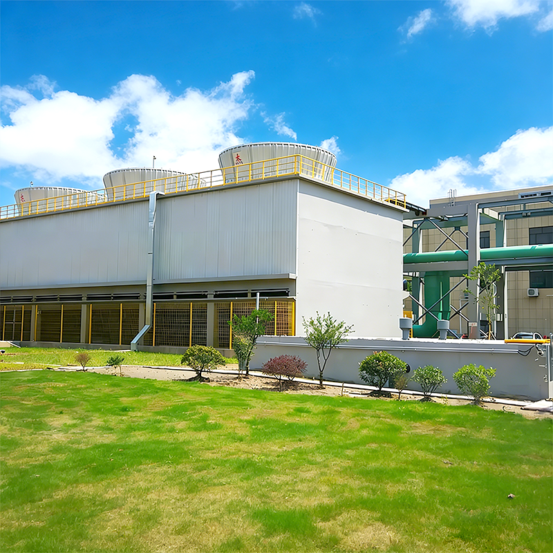
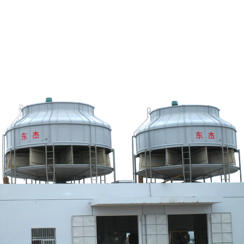
For large power, steel, or industrial projects, the diagram may show a steel structure tower rather than a factory-assembled FRP unit. The layout then includes structural columns, access stairs, and a larger basin, and the drawing package usually involves civil and structural disciplines as well as mechanical.
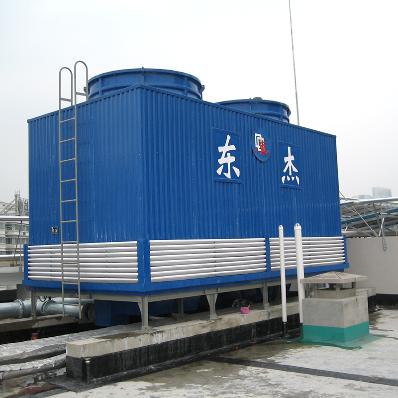 Counterflow Steel Structure Cooling Tower (DF Series)Steel-structure counterflow tower with compact low-height layout, galvanized support, and low-noise operation, suited to large industrial projects needing structural coordination and reliable corrosion protection.View Product →
These checks are simple, but they catch most of the problems that show up later in commissioning.
A chiller and cooling tower diagram is a shared language between the design team, the equipment supplier, and the site crew. When the drawing is clear, installation and commissioning go more smoothly. When something is missing, it usually appears as a question on site.
Our team at Zhejiang Dongjie Cooling Tower has spent years reading these drawings alongside engineers and contractors. We design and manufacture cooling towers for power, petrochemical, metallurgy, chemical, HVAC, new energy, and environmental projects, and we support customers from selection through delivery. If you are reviewing a diagram and want a second set of eyes on the tower side, take a look at our cooling tower range or send the drawing over. We are always glad to talk through the details.
Related Products
In industrial cooling systems, water is both the most essential element and the most common source of operational problems. Scale, corrosion, fouling, and micr...
READ MOREWhen a process line needs to hold a reactor at 5 °C, a chiller is the obvious choice. When the same plant needs to reject a large amount of waste heat from a c...
READ MOREA plant engineer managing a 2 MW injection molding process was facing a familiar problem. The open cooling tower was letting suspended solids into the mold coo...
READ MOREInduced draft cooling towers are the quiet workhorses behind many industrial processes. You will see them at power stations, chemical plants, steel mills, and ...
READ MOREIndustrial facilities that rely on continuous thermal processes, from power generation to chemical manufacturing to large scale HVAC systems, depend heavily on...
READ MOREAn FRP cooling tower is a heat rejection unit whose casing, structural frame, and often its cold water basin are built from glass-fiber reinforced polymer rath...
READ MORE
dj@djcoolingtower.com
+86-0575-82433555 (Extension 0)
+86 130 6551 5158 Manager Zhang
